Shaft Voltage, Shaft Current
I. Shaft Voltage
Definition: The voltage between the rotating shaft and the casing or the terminal voltage between the two bearings of the motor.
Shaft voltage is divided into four categories: magnetic circuit imbalance, residual magnetism, static electricity, inverter power supply. Among them, inverter power supply is the main source of shaft voltage.
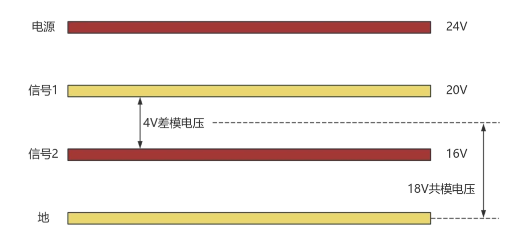
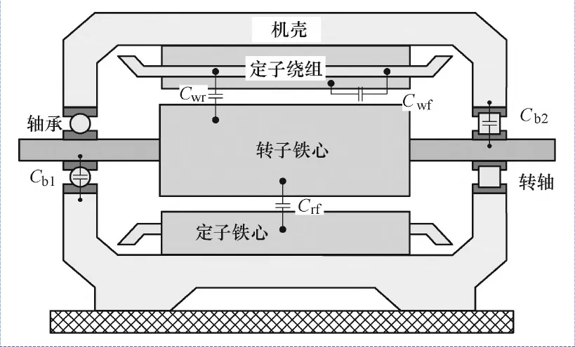
Due to the new generation of power electronic devices switching speed and voltage level of improvement, the converter switching action of the instant will produce a high amplitude, high dv/dt common mode voltage (Figure 1), when the high-frequency common-mode voltage is applied to the end of the motor windings, the common-mode current will be through the motor through the internal stray capacitance (Figure 2) path in the bearing at the ends of the induction of a large amount of axial voltage and axial current, which will lead to the bearing corrosion, shortening the service life of the bearing, and endangering the two bearings. This will shorten the service life of the bearings and jeopardise the reliability and safety of the inverter motor operation.
Shaft voltage discharge or not depends on the comparative relationship between the value of the shaft voltage and the value of the oil film withstand voltage, which means that the size of the shaft voltage and whether or not galvanic corrosion will be produced, there is no necessary connection.
The oil film is with the motor working conditions change, between 0 thickness and better thickness is constantly changing.
Therefore its voltage strength is also always changing. When the oil film is thin, a very low voltage can break it down, and when the oil film is of good quality, a higher voltage is needed to break it down. Therefore, it is not possible to give a safe shaft voltage for a changing oil film state.
Axial current: mainly divided into capacitive axial current, EDM axial current, rotor grounding axial current and circulating axial current four categories. At present, the harm produced by the motor shaft current is mainly caused by the inverter power supply drive system, that is, EDM shaft current, the current pulse is about 0.5A-3A.
Second, the harm of electrical corrosion
In the past, the voltage platform, rotational speed and motor power of new energy vehicles are relatively low.
However, in recent years, the four high development of automotive electric drive system (high voltage, high power, high frequency, high speed) two-way compression of the bearing oil film resistance to galvanic corrosion living space:
(1) Higher voltage platform lifts the shaft voltage;
(2) The greater power makes the induction energy more;
3) Higher switching frequency then makes the oil film attacked more frequently;
(4) In order to adapt to the high speed and lower viscosity of the lubricant / grease makes the oil film thickness is thinner, the ability to become worse.
As a result, galvanic corrosion is becoming more common in new energy tram systems.
In addition, there are many systems powered by variable frequency motors where galvanic corrosion failure due to microcurrents is also common.
Common galvanic corrosion phenomenon:
Large voltage corrosion (Figure 3)
Microcurrent corrosion (Figure 4)
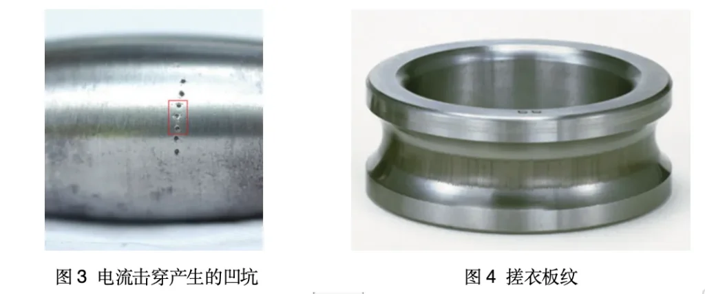
It is worth noting that rubbing pattern is not the main failure mode of bearings, it is a secondary damage phenomenon of bearings.
When a tiny current passes through the bearing, it will not form the large galvanic pits formed when the voltage is too high, but tiny galvanic pits will appear on the raceway surface.
With continuous rotation, after a period of time on the raceway of the tiny corrosion pits will show a certain aggregation, coupled with the rolling body through the formation of corrosion pits of mechanical resonance, will form what we often call ‘rubbing board’ pattern.
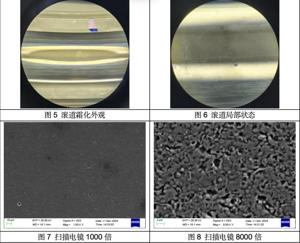
If the motor in a wide range of variable speed operation (inverter motor), or micro-current occurs early, galvanic corrosion pits are not regular, will be more inclined to present a similar sandblasted surface frosting appearance (Figure 5, Figure 6), but also a little similar to the lubricating particles caused by contamination of the coarsening of the rippled fatigue of the metal surface (but under the microscope to present a different).
Scanning electron microscopy analysis of the frosting appearance described above, as shown in Figures 7 and 8, demonstrates that the frosting appearance is early galvanic corrosion failure.
Third, how to test the shaft current and shaft voltage
1. First, ensure that the test motor is well grounded. It is recommended that the system is grounded at a single point to reduce the potential difference between different grounding points may cause test interference.
2. With a flexible low-friction conductive probe and motor shaft contact (the contact point can be the end of the shaft, can also be the circumference of the shaft) will lead to the shaft electrical signals, and the oscilloscope test probe signal end is connected to the oscilloscope test probe grounding clamp is connected to the motor chassis.
3. In accordance with the test line shown in Figure 9 after the completion of the connection, in the motor static, using a multimeter to measure the chassis connecting line to the rotor shaft connecting line between the resistance to verify that the resistance value is less than 5 ohms. (If it is a single motor, and the front and rear bearings are insulated bearings, this requirement does not apply)
1
Single Point Grounding
Firstly, ensure that the test motor is well grounded. It is recommended that the system be grounded at a single point to reduce the potential difference between different grounding points that may cause test interference.
2
Correct Connection
Use a flexible low-friction conductive probe to contact with the motor shaft (the contact point can be the end of the shaft or the circumference of the shaft) to draw out the shaft electrical signal and connect it with the signal end of the oscilloscope test probe, and the grounding clip of the oscilloscope test probe is connected with the motor casing.
3
Verify the resistance
In accordance with the test line shown in Figure 9 after the completion of the connection, in the motor static, using a multimeter to measure the chassis connecting line to the rotor shaft connecting line between the resistance to verify the requirements of the resistance value of less than 5 Ohms. (This requirement does not apply if the motor is a single motor and the front and rear bearings are insulated).
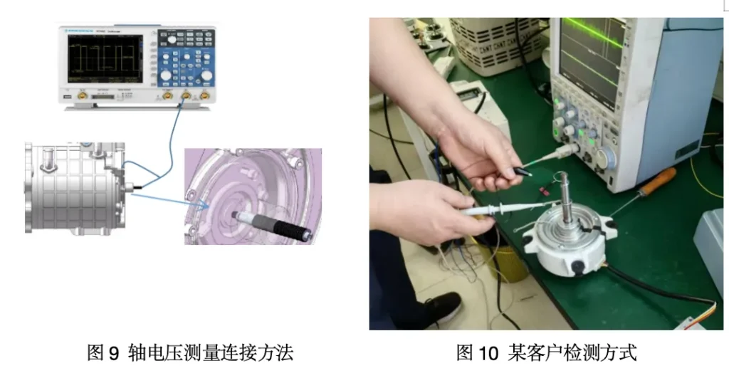
As can be seen from Figure 9, the need for flexible connectors at the rotating shaft, otherwise it is easy to cause measurement errors.
Figure 10 is a customer site test shaft voltage using the form of tin to make two rings, one side of the bearing with the outer ring contact (not moving), the other side of the contact with the rotor shaft (rotor shaft rotation), such a form is likely to cause human error in measurement.
Fourth, the existing prevention and control measures
How to limit the occurrence of galvanic corrosion of bearings, roughly divided into three categories: choke limit, insulation blocking and bypass channeling.
Restriction
In the output of the inverter placed on the choke ring or choke coil to limit. However, this method can not eliminate the common mode voltage of the motor, and automotive drive motors are precisely the common mode voltage breakdown caused by the most serious bearing corrosion. In addition, this method usually requires a large installation space.
Blocking
The path of the shaft current is cut off by insulating the bearings or associated parts. If ceramic ball bearings are used, the problem of galvanic corrosion in this bearing can basically be solved.
However, if an insulating coating is used, the high-frequency impedance of the insulating layer is very low at high frequencies and may not be able to withstand voltage shocks. Of course even if the insulated bearing itself is protected, the shaft and the load end behind it are hardwired, and in the case of electricity on the shaft, the electricity will be exported through the connection point to the load end, where it will find the weakest point to be released.
Bypassing
Increase the low resistance bypass, so that the charge through this increased bypass drain, so that the shaft voltage is reduced, the current through the bearing will be very small, and reduce the risk of voltage breakdown, effective protection of bearings. The mainstream of the market diversion programme has four types of conductive carbon rods, conductive oil seals, conductive grease and grounded conductive ring.
